
Acoustical considerations for large rooftop units
Rooftop HVAC equipment provides enticing features for the design engineer and cost advantages for the owner. Fans, ventilation equipment, a heat source, compressors, condenser, and controls are assembled in a compact unit ready for installation on a roof curb. Manufacturers assemble, test, and rate the entire package as a system. The advantage of locating the unit on the roof frees up floor space in the building.
The convenience of packaged
equipment has driven a demand for
increasingly larger units. Packaged
rooftop equipment is now available
from several manufacturers in sizes up
to and beyond 150 tons. The larger
units' design has also been updated to
meet industry demand for improved
efficiency and indoor air quality.
Greater flexibility in fan choices,
equipment options, and unit
configuration is also becoming
available.
With these larger units, many factors
need to be considered in the design of
the building, such as increased
structural support, larger electrical
service, etc. Unfortunately, the
increased sound levels produced by
these units are sometimes overlooked.
Following a fixed set of acoustical
practices used with smaller units may
not sufficiently attenuate the increased
sound levels of the new larger units.
Large packaged rooftop units can be
installed without creating noise problems
in the occupied spaces, but not without
appropriate consideration. An acoustical
review using the source-path-receiver
acoustical model (see sidebar, p. 3
"Defining an Acoustical Model") early in the
design process is critical to achieving the
desired sound levels.
The discussion that follows:
• Illustrates how an acoustical analysis
affects design decisions and helps the
installation succeed in terms of first cost
and occupant satisfaction.
• Outlines general and specific acoustical
considerations for very large rooftop
units.
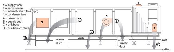
Figure 1. Large rooftop: Four types of sound paths
Acoustical Analysis,
Step by Step
An acoustical analysis consists of five
basic steps:
Step 1: Set acoustical goals for the
finished space. It is critical to establish
the acoustical goals for the finished space
at the outset of any HVAC project. There
are always implicit, often subjective,
expectations for the background sound
level in occupied spaces. It is much easier
to produce a successful installation if you
understand these expectations before
designing the installation. The risk involved
in waiting until the unit is installed is
considerable because the cost of quieting
an installed unit always exceeds the cost
of applying the same treatment during
installation.
Also be aware that once a unit is installed,
some changes, e.g., switching to a
different fan size, will not only be
expensive but could affect the unit’s UL
rating.
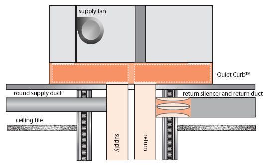
Figure 2. High level of path attenuation
Remember these three points when
defining desired sound levels:
1. As a general rule, lower sound levels
cost more to achieve.
2. All spaces in the building do not have
the same sound requirement; a lowcost,
quiet installation takes advantage
of this point.
3. Successful acoustics requires a team
effort. The team should include the
owner, engineer, architect, equipment
manufacturer, and contractor.
Sound goals will vary depending on how
the space is used. Once the sound
goals are understood, state them using
an appropriate descriptor such as NC
(Noise Criteria) or RC (Room Criteria).
Step 2: Identify each sound path and
its elements. Large rooftop HVAC
installations have four types of paths
(Figure 1, p. 2):
1. Airborne sound follows the airflow
path. Supply airborne sound travels the
same direction as the supply air. Return
airborne sound travels against the
airflow direction. Airborne sound also
includes sound generated by the
ductwork and diffusers.
2. Breakout sound passes through
duct walls into the plenum space, then
through the ceiling and into the room.
3. Roof transmission sound passes
through the roof deck (both within and
outside the roof curb), plenum space,
and ceiling into the room.
4. Structure-borne sound differs from
the other sound paths in that it is
vibrational energy transmitted through
the framework of the building. This
energy may come directly from the
vibration of the sound source or from
airborne sound energy transferred to
the structure.
Step 3: Perform a path-by-path
analysis. Once each path has been
identified, individual elements can be
analyzed for their contribution. For
example, the supply airborne path
includes various duct elements (e.g.,
elbows, straight duct, junctions,
diffusers) and a room-correction factor.
Algorithms available from ASHRAE can
calculate the acoustical effect of each
duct element. The effect of changing
an element (e.g., removing the lining
from a section of ductwork) can be
examined. A software tool like the
Trane Acoustics Program™ (TAP)
simplifies this process.
This step typically entails at least two
iterations for each path. The first pass
establishes the acoustical performance
of the initial design. Subsequent
passes determine the effect of adding
various acoustical treatments.
Step 4: Sum the results to determine
the acoustical performance of the
installation. The sound level at a
receiver location is the sum of all the
sound paths for that location, both
from the rooftop unit and from other
sound sources. After the contributions
of the individual paths are calculated,
add them together to determine the
sound level at the receiver location. If
the sum exceeds the goal, another
round of path attenuation calculations
is required.
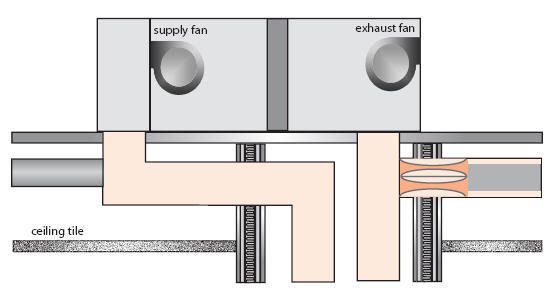
Figure 3. Low level of path attenuation
Step 5: Compare the summations
with the acoustical goals in the
context of the project budget. Once
a design meets the acoustical goals for
the project, everyone on the team
must understand the work and costs
required to implement the design. It
may also be prudent to review the cost
of meeting the acoustical goals and
reconsider equipment options that
were initially rejected due to cost.
Additional guidance on creating a
rooftop sound analysis can be found in
the Trane application manual and
ASHRAE Journal article listed in the
reference section.
Specific Considerations for
Very Large Rooftops
As rooftop unit size increases, building
and duct construction details play a key
role in determining the sound levels in
the occupied space. Review of
generalized acoustical models for large
rooftop applications indicate that the
three critical sound paths are return
airborne, return breakout, and supply
breakout. The models also show that if
acoustics are not considered, an
application can have sound levels that
are too high. However, acceptable
sound levels in the occupied space can
be achieved with proper attention to
unit selection and application details.
This section uses a generalized
acoustical model to show how both
unit and application choices impact the
potential NC in an occupied space. As
described in the previous section, an
accurate estimate of sound pressure in
the occupied space requires a unique
acoustical analysis for each application.
The NC values in this section are based
on a generalized model and do not
indicate what the sound will be in any
particular application.
Quiet the Source. One way to lower
the sound level in the occupied space
is to reduce the sound produced by the
rooftop unit. Operating conditions, fan
selection, optional equipment, and
cabinet choices all have an impact on
the amount of sound produced by the
rooftop unit.
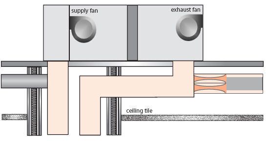
Figure 4. Low level of path attenuation
Solid Surfaces. Some rooftops come
standard with solid double-wall
construction throughout. This helps
prevent dirt and moisture from
adhering to the surfaces but makes the
surfaces less absorptive to sound.
For applications that do not require all
solid surfaces in the airstream, one or
more sections of the unit may be
available with a sound absorbing lining
(either with or without a perforated
plate) and a moisture barrier to
separate the lining from the airstream.
Units rated following ARI 260 test
methods indicate that the addition of
lining can result in a sound reduction
on the order of 4 to 6 dB in the critical
125 Hz octave band.
Fan Configuration. Units may be
configured with supply fan only, supply
and exhaust fan, or supply and return
fan. Although unit configuration isn't
generally based on acoustical
considerations, each choice has a
unique impact on sound produced by
the unit. If design flexibility allows,
check all available configurations to find
the one that is best for the application.
Supply Fan Only. This configuration
will have higher sound levels at the
discharge opening but relatively low
levels at the return. A supply fan only
configuration tends to perform well
overall because of the plenum
attenuation created by the heat and coil
sections on the discharge side, and
mixing and return sections on the inlet
side of the fan (see Figure 2).
The supply fan is the dominant sound
source in rooftop units. To help
attenuate the supply fan discharge
sound, consider using the largest
supply fan available in each tonnage
size. Larger fans run at a lower speed
and are typically quieter. Unit
selections have shown a 10 dB
reduction in the 250 and 500 Hz octave
bands at 32,000 cfm and 5" of fan
static for some fans. (Of course, unit
sound data is dependent both on fan
type and operating point, so check all
available fan selections for a particular
operating point.)
In general, moving to a larger fan will
lower the sound level for a given flow
and pressure drop. However, moving
to a larger fan may also move the fan
closer to a region where "acoustical
stall" occurs (see the sidebar "Acoustic
Stall").
The cost implication of changing the
fan type should also be considered. It
may be more cost effective to quiet the
unit/installation by another method.
Return/Exhaust Fan. In some cases
the addition of a return fan will lower
the discharge sound level; however,
return and exhaust fans increase sound
levels at the return opening. The model
shows that switching from a supply fan
only to a supply and exhaust fan
configuration increases the sound in
the occupied area below the rooftop by
3 NC. Switching to a supply and return
fan may result in an 11 NC increase
over the supply fan only unit. The
change in supply sound depends on
both the type and operating point of
the return/exhaust fan used.
Sound radiated from the return
opening comes from the inlet of the
supply fan plus the exhaust or return
fan. Adding a return fan may cause the
return airborne and breakout sound
paths to set the sound levels in the
occupied space. Return fans generally
result in higher sound levels in a space
than exhaust fans when the inlet to the
return fan is mounted directly above
the return ductwork. Sound from a
sidewall-mounted exhaust fan is
attenuated by the plenum effect of the
return section. Also, different fan types
and operating points may be used for
the two fans so the sound created will
be unique to each fan at each operating
point.
To lower the sound being transmitted
through the return air opening,
consider the following:
1. Review the sound data for return vs.
exhaust fan for your conditions to
determine which configuration
results in the lowest sound levels.
Also look at all fan options for each
configuration. Changing to a larger
supply and return fan size can have a
significant effect. A typical selection
showed switching to the larger
return fan at 27,000 cfm and 2" of fan
static will reduce the 250 and 500 Hz
bands by 4 and 5 dB respectively.
2. Consider using a horizontal
connection (if available) for the unit
return and running the return duct
over the roof before penetrating the
building. Running the return duct
over the roof has several
advantages:
• Low frequency sound will break
out of the duct walls to the
outdoors, thereby reducing the
sound entering the building.
• Lining the duct run on the roof will
provide attenuation at the mid and
upper frequencies.
• The duct penetration can be
moved to a non-sound sensitive
area of the building.
Quiet the Sound Paths. Quieting the
unit helps, but the greatest acoustical
benefits come from looking at how the
unit is integrated with the building.
Changing the installation to attenuate
the critical sound path(s) can have a
dramatic effect on sound levels in the
occupied space.
Location. Locating a large rooftop unit
over a sound-sensitive area will either
result in unacceptably high sound
levels in the occupied area or add
considerable cost to prevent the sound
produced by the unit from reaching the
occupants. Consider locating the unit
over a non-sound sensitive area, even if
it means running the supply and return
ducts over the roof. External runs of
duct can provide attenuation of the
supply and return airborne sound
before the roof penetration is made.
Roof Structure. Supply duct breakout
has commonly been the critical sound
path for rooftop units, but problems
with roof transmission are on the rise.
This is perhaps due to an increased
awareness and attention to attenuating
the discharge path, but it may also be due to the increased use of lightweight
roof structures.
Sound radiated from the compressors,
condenser fans, exhaust fans, and the
casing of the unit will impinge on the
roof surface surrounding the unit. A
lightweight roof (metal deck with
insulation and ballast) provides minimal
resistance to the transmission of
sound.
The poor transmission loss
characteristic of roofs often becomes
apparent when taking sound readings
on problem jobs. With all sound
producing equipment off, place a radio
at moderate volume on the roof near
the unit and go inside and listen. If you
can hear the radio, roof sound
transmission is likely to be a problem.
Increasing the transmission loss of the
roof generally means adding mass to
the roof--typically a concrete slab--
around the unit. Thickness and area of
the slab are dependent on how much
transmission loss is required to meet
the sound goals for the job.
Also avoid unit placement on a flexible
roof structure that will transform
vibration from the unit into sound that
radiates into the building. As with all
rooftop units, placing the unit in a
location over a column or other rigid
support element will minimize this
problem. Proper support is especially
important for larger units because of
the increased mass and vibration
energy due to larger compressors and
fans, and high airflow.
Duct Chase. When a large rooftop unit
serves several floors of a building via a
duct chase, properly positioning the
unit over the chase will have a dramatic
effect on the sound levels in the
occupied areas near the unit.
Figure 2 shows a construction that will
provide a high level of path attenuation.
A special curb is used that provides
unit attenuation and brings the supply
and return openings closer so they can
be matched up with the chase
opening. Notice that a short run (height
of one floor) of return duct is installed
inside the chase; this provides some
additional return breakout transmission
loss that lowers the sound levels in the
chase.
Return air openings at the floors are
supplied with a silencer and a short run
of lined return duct to provide
additional attenuation and move the
return airborne sound away from the
shaft wall. Round duct is used for the
supply to reduce duct breakout near
the chase wall. The generalized model
shows that removing the short run of
return duct from the configuration
shown in Figure 2 results in an
increase of 10 NC for the supply fan
only unit and 12 NC for the supply and
exhaust fan unit.
Locating either the supply or return
opening over the chase and then
ducting the other opening to the chase
is not recommended (see Figure 3 and
Figure 4), except for jobs using a
poured concrete roof curb. Poured
concrete roof curbs are typically used
in conjunction with a concrete roof slab
to minimize roof transmission. With
the concrete curb, the supply opening
should be located over the shaft, as in
Figure 4, with the return duct run
inside the concrete curb to the shaft.
In all chase applications, it is important
that the chase is run all the way to the
roof deck and is sealed with acoustical
mastic to the roof deck. Supply and
return air duct penetrations though the
shaft wall must also be sealed to
prevent sound from leaking out of the
shaft.
General Considerations.
Operate the Unit as Designed. It is
quite common to overestimate the
system static pressure required to
achieve design airflow. This results in
the installation of larger motors and/or
higher fan rpm than required to
overcome the actual static pressure. To
compensate for the additional static,
the air terminal device balancing
dampers are more restricted than
necessary. These "over-aired" systems
waste energy and force the units to
generate excess sound.
To minimize noise, operate the rooftop
at the lowest possible pressure in the
duct. After installing the rooftop unit
and its associated air distribution
system, it must be properly air
balanced by qualified air balancing
technicians using calibrated air
measuring devices. The airside system
should be balanced to achieve the
desired airflow at all terminal outlets
while maintaining the lowest possible
fan rpm and system static pressure.
Utilizing the fan pressure optimization
control strategy is an excellent way to
achieve this on VAV systems. (See
"Energy Saving Strategies for Rooftop
VAV Systems", Engineers Newsletter
vol. 35--4, 2006.)
Proper Duct Design. The fans in the
rooftop unit are not the only sound
source in the HVAC system.
Aerodynamic noise is generated at
duct fittings, e.g., junctions, elbows,
diffusers, dampers, and take-offs. The
sound power levels generated at these
fittings are dependent on airflow
turbulence, fitting geometry, and
airflow velocity. Meeting the acoustical
goals for the job requires all sources of
sound to be considered.
Several guidelines for minimizing the
generation of aerodynamic noise are
available. The ASHRAE book, "A
Practical Guide to Noise and Vibration
Control for HVAC Systems" is a good
reference source for designing quiet
HVAC systems as are the ASHRAE
Handbooks. Careful duct design is
especially important at the discharge of
the rooftop unit. Air leaving a rooftop
unit tends to be turbulent; as a result,
pressure drop and generated sound
will exceed what is normally predicted
for fittings near the unit.
Closing Thoughts
Don't let noise ruin the advantages and
convenience of large rooftop units.
Review the acoustical goals for the
occupied space during the building
design process. Use an acoustical
analysis to identify and attenuate the
critical sound paths so the sound goals
for the job can be achieved. Yes, this
adds cost and takes time but not nearly
as much time and money as fixing a
problem job.
Artykuł pobrano ze strony: http://www.trane.com/CPS/Uploads/UserFiles/EducationalResources/admapn032en_0509.pdf